115 Volt Electric Motor Wiring Diagram
Changing the operating voltage of a motor is just a matter of switching a few wires around on the motor's terminal plate. When you make use of your finger or perhaps the actual circuit with your eyes, it is easy to mistrace the circuit.
115 Volt Ac Single Phase Motor Armature And Fields Wiring Diagram
Units with these plugs use between 110 and 120 volts standard household electricity.

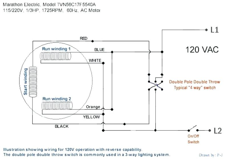
115 volt electric motor wiring diagram. By switching these wires, you change internal wiring for the run windings and the start windings from a parallel hook up for 115 volts to a. Each component ought to be placed and linked to different parts in specific way. However, this diagram is a simplified version of this arrangement.
Inst maint & wiring_5.qxd 20/11/2015 11:37 am page 7 This makes the process of. These tips can be used on most ele.
When you make use of your finger or perhaps the actual circuit with your eyes, it is easy to mistrace the circuit. 115/230 volt motor wiring diagram from wholefoodsonabudget.com print the wiring diagram off plus use highlighters to trace the signal. The text neutral line confuses me).
Painted and stainless steel for both fresh and saltwater lifts from 3/4 hp through hp. Generally, you have 3 wires going to the motor for ac. A universal electric motor is designed to operate on either alternating current or direct current (ac/dc).
Electric motor wire marking & connections. A hot, a neutral, and a ground. Baldor electric motor wiring diagram elegant ge electric motors.
The key is to make sure you connect the wires to the proper terminals in the plug. 1 trick that we 2 to printing a similar wiring plan off twice. Collection of travel trailer wiring schematic.
Wiring diagram single phase electrical motor 115 volts ford. It is a series wound motor. I understand that it really doesn't make a difference, as long as my line (in) is the side that is switched (which is is), so the motor.
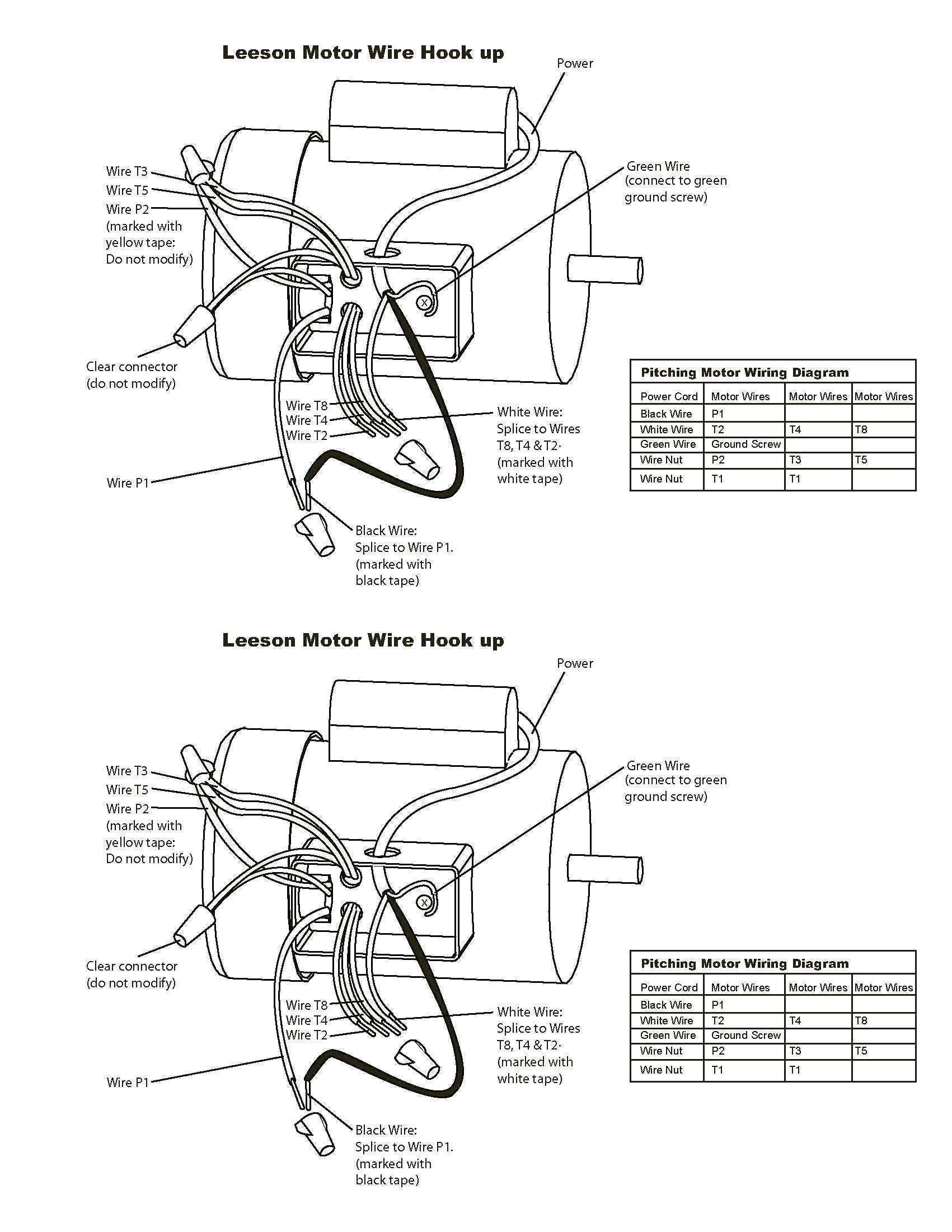
On the other hand, the diagram is a simplified variant of this arrangement. The larger prong is neutral and the smaller prong is the hot connector. For specific leeson motor connections go to their website and input the leeson catalog # in the review box, you will find connection data, dimensions, name plate data, etc.
It s supposed to help each of the common person in creating a suitable system. Then just change out each wire one at. 115 230 volt motor wiring diagram.
In this video, jamie shows you how to read a wiring diagram and the basics of hooking up an electric air compressor motor. A flat plate hoist, using an electric motor to drive a worm reduction, is one of the most. The information and suggestions that were elaborated above ought to be a terrific kick start, though.
New pump's diagram suggests line on l1 (note: Wiring diagram not only provides in depth illustrations of what you can perform, but also the methods you ought to. Each component ought to be placed and linked to different parts in.
If not the structure won t function as it should be. Leeson 115 230 engine wiring century ac diagram diagrams volt single phase electric motors for baldor practical machinist biggest emerson electric assist uk wire a gould 2 hp 3450 rpm marathon wait 68 reversing switch 480 full i have actually chinese made dual sd need electrical energy 101. Higginbotham on friday, february 15th, 2019 in category wiring diagram.
This diagram also covers certain models of: 1 trick that we 2 to printing a similar wiring plan off twice. It is provided with a field winding on the stator which is connected in series with a commutating winding on the rotor.
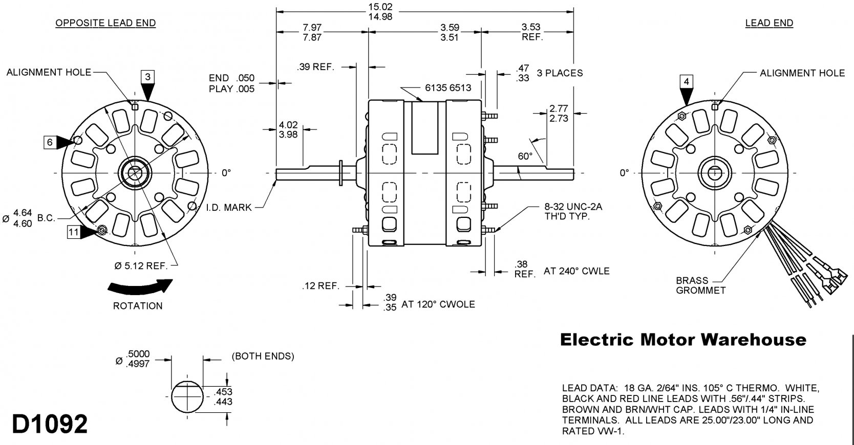
I'm wiring a new pump (usq1072) for 115v operation the old pump's diagram (115v) has line on l2. Airflow airflow airflow airflow * * these diagrams are current at the time of publication, check the wiring diagram supplied with the motor. Just follow the wires from the plug to the motor like you would with an electric laundry dryer, or other such 3 phase wired equipment.
Print the wiring diagram off plus use highlighters to trace the signal. A wiring diagram is a streamlined conventional photographic representation of an electric circuit.
Century Ac Motor Wiring Diagram 115 230 Volts Wiring Diagram
How to wire a baldor motor 115/230 cat no L1406t it has six wires wich do I conect

115 Volt Motor Wiring Diagram wiring diagram


115 230 Volt Electric Motor Wiring Diagram Wiring Diagram

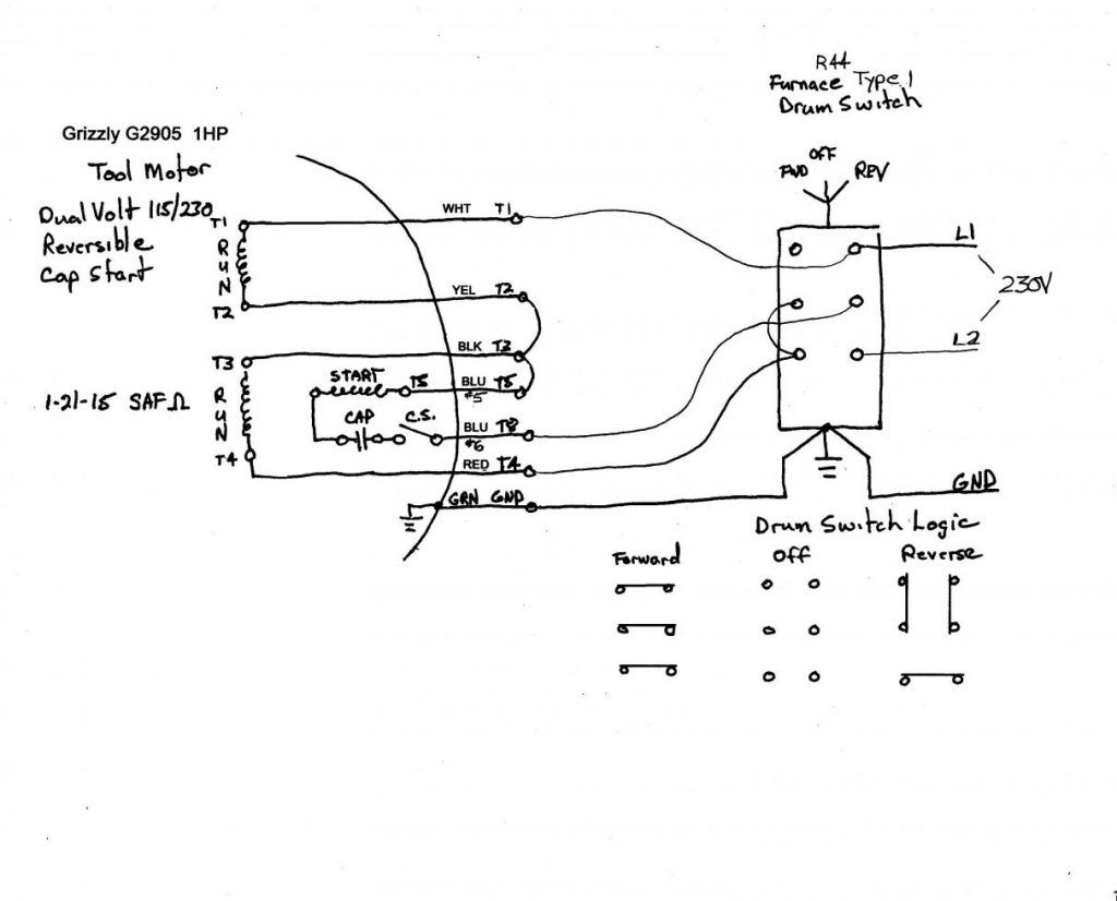
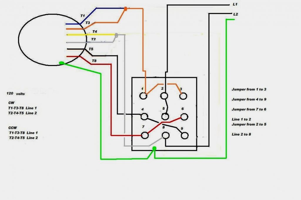
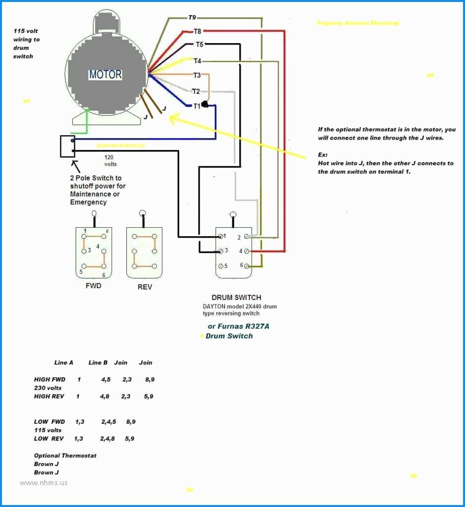
I am trying to connect this single speed 8 lead 115/220 volt motor to this reversing drum switch
Century Ac Motor Wiring Diagram 115 230 Volts Wiring Diagram

I have a dayton 5k436j motor on a lathe, set up for 115 volt. I currently have terminals t1, t3
Dayton Fan Motor Wiring Diagram 1/40 hp, 1550 RPM, 115 Volt, 3.3" diameter Dayton Electric
115 230 Volt Electric Motor Wiring Diagram Wiring Diagram

115 Volt Ac Motor Wiring Wiring Diagrams Thumbs Baldor Motor Wiring Diagram Wiring Diagram
Wiring Diagram For Freezer 115 Volt schematic and wiring diagram


Grainger Drum Switch 115 Volts Wiring Diagram

Dayton 1/2 Hp Motor Wiring Diagram General Electric Motor Wiring Diagram Page 1 Line 17qq Com
115 Volt Motor Wiring Diagram


[DIAGRAM] Century Electric Motors Wiring Diagram 115 Volt 316p760

115 230 Volt Motor Wiring Diagram easywiring
115 Volt Ac Motor Wiring Wiring Diagrams Thumbs Baldor Motor Wiring Diagram Wiring Diagram
[DIAGRAM] 115 Volt Motor Wiring Diagram Cw

Century Motor Wiring Diagram Cadician's Blog