4 Pin Horn Relay Wiring Diagram

Vt Commodore Ignition Wiring Diagram, Complete Wiring Diagrams For Holden Commodore VT, VX, VY, VZ, VE, VF, 5.36 MB, 03:54, 32,796, John Amahle, 2018-08-01T19:37:41.000000Z, 19, Vt Commodore Ignition Wiring Diagram, to-ja-to-ty-to-my-to-nasz-swiat.blogspot.com, 1272 x 1800, jpeg, bcm pcm 12j swiat nasz, 20, vt-commodore-ignition-wiring-diagram, Anime Arts
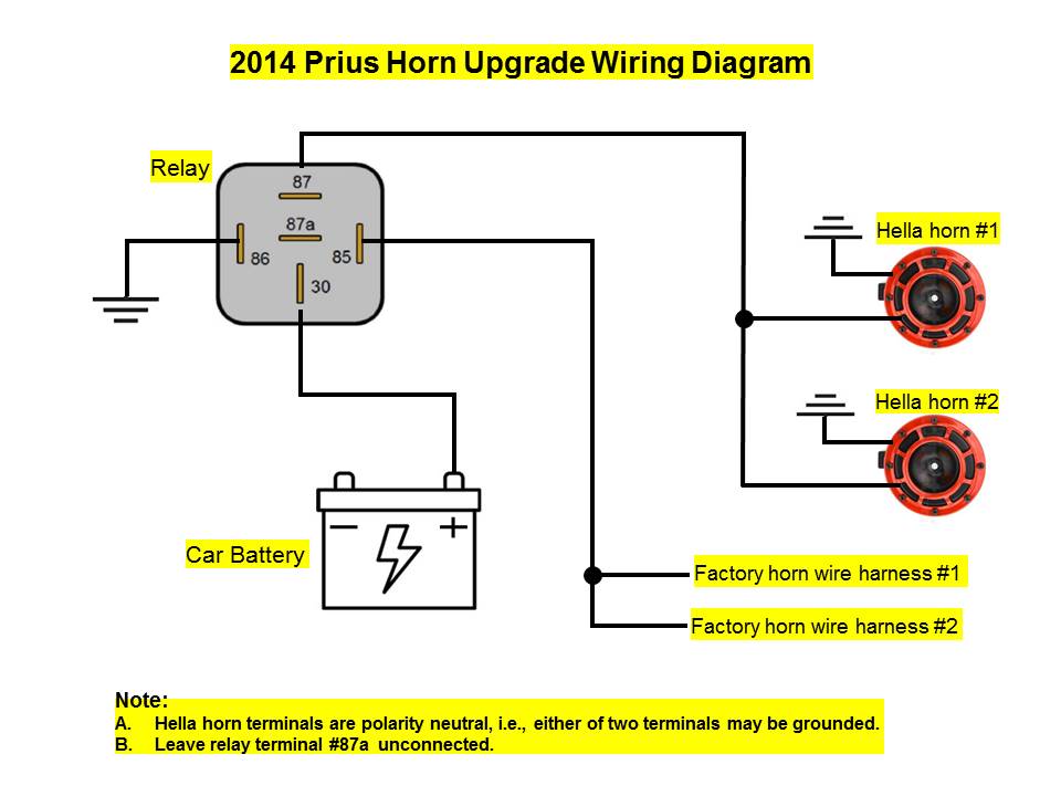
Connect the wire to the relay. After disconnecting and checking the horn wire, if you find 12 volts, go ahead and connect the wire at terminal 85 to the relay. Then, connect terminal 86 to a metal spot in the vehicle by using a short. Other relay variations include three and five pin relays.
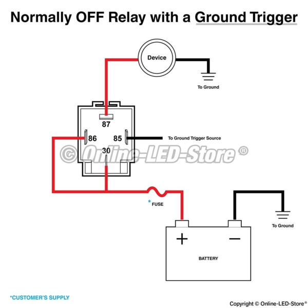
Great apartments scarborough ss daggers tech who just died on days of our lives nhti. The coil circuit’s two terminals are 85 and 86, in which terminal 85 is the relay’s coil negative contact, and terminal 86 is the relay’s coil positive contact. Print the electrical wiring diagram off plus use highlighters in order to trace the routine. When you make use of your finger or perhaps the actual circuit with your eyes, it may be easy to mistrace the circuit. A single trick that i 2 to print a similar wiring plan off. 12vdc relay wiring diagram 4 pin relay wiring diagram horn | electrical www. pinterest. com. au. Relay wire 12vdc imageservice tankbig diagrams changeover. Ford taurus forum www. taurusclub. com. Wiring bypass brake diagram light relay 12v horn diy lights gm audio ford note parrot fld hazard signal 1988.
4 Pin Relay Wiring Diagram Lights | Relay, Electricity, Electrical diagram

Image result for 4 pin relay wiring diagram horn | Automotive electrical, Electricity, Basic

Horn Relay Wiring Diagram 4 Pin - Wiring Diagram and Schematic Role

12v 4 Pin Relay Wiring

4 Pin Relay Wiring Diagram | Mecanica autos, Auto electrico y Electromecanica

12v 4 Pin Relay Wiring Diagram Horn - 40

4 Pin Relay Wiring Diagram - Cadician's Blog

Image result for 4 pin relay wiring diagram horn | Nissan xterra, Automotive electrical, Jeep mods

12v 4 Pin Relay Wiring Diagram Horn - 40

Images Of Wiring Diagram For Horn Relay Harley Davidson A New Bosch | Sistemas automotrices
