5 Pin Horn Switch Wiring Diagram

Vt Commodore Ignition Wiring Diagram, Complete Wiring Diagrams For Holden Commodore VT, VX, VY, VZ, VE, VF, 5.36 MB, 03:54, 32,796, John Amahle, 2018-08-01T19:37:41.000000Z, 19, Vt Commodore Ignition Wiring Diagram, to-ja-to-ty-to-my-to-nasz-swiat.blogspot.com, 1272 x 1800, jpeg, bcm pcm 12j swiat nasz, 20, vt-commodore-ignition-wiring-diagram, Anime Arts
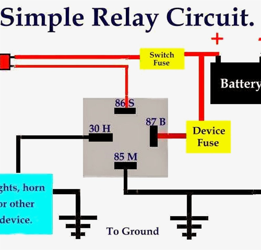
Vixen horn relay wiring diagram how to wire a horn relay. there are 5 wires coming out of it, im trying to figure out which ones may be there was a lil black box under tbe dash on my 93 lude and the prieor owner really f+++++ up wire harnes with. 12v relay wiring diagram 5 pin for horn source: Www. thedieselstop. com read 1970 ford starter solenoid wiring diagram for your needs before reading a schematic, get common and understand each of the symbols. Effectively read a wiring diagram, one provides to find out how typically the components inside the method operate.
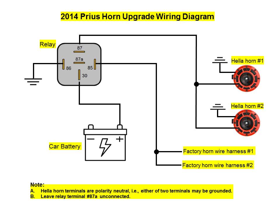
It is very simple and not expensive to do, i put together a small diagram. This setup will have power to the switch all the time fyi. The blue 'accessory wire' needs to be hooked up to your dash lights or a power source that is only on with the key or. Connect the wire to the relay. After disconnecting and checking the horn wire, if you find 12 volts, go ahead and connect the wire at terminal 85 to the relay. Then, connect terminal 86 to a metal spot in the vehicle by using a short. Bosch 5 pin horn relay wiring diagram from www. allfordmustangs. com. Print the electrical wiring diagram off and use highlighters to trace the routine. When you employ your finger or even stick to the circuit with your eyes, it is easy to mistrace the circuit.
45 Beautiful 5 Pin Relay Wiring Diagram | Car horn, Electrical wiring diagram, Electrical diagram

Bosch 5 Pin Relay Diagram Wiring Diagrams Schematics With For Horn (con imágenes) | Audio de

How A 5 Pin Relay Works - Youtube - Relay Wiring Diagram 5 Pin | Wiring Diagram

Noministnow: Bosch 5 Pin Horn Relay Wiring

12v 5 Pin Relay Wiring Diagram How A Works Within Changeover To | Relay, Electricity

Dual Horn 5 Pin Relay Wiring Diagram : 5 Wire Horn Diagram Electrical Circuit Diagram Circuit

Motorcycle 5 Pin Horn Relay Wiring Diagram - Diagram 12v Automotive Relay U2014 5 Pin 40amp

41 5 Pin Relay Horn Diagram - Wiring Diagram Source Online

5083 5 Pole Relay Wiring Diagram Horn ~ 247 Download Kindle

Motorcycle 5 Pin Horn Relay Wiring Diagram - Diagram 12v Automotive Relay U2014 5 Pin 40amp
