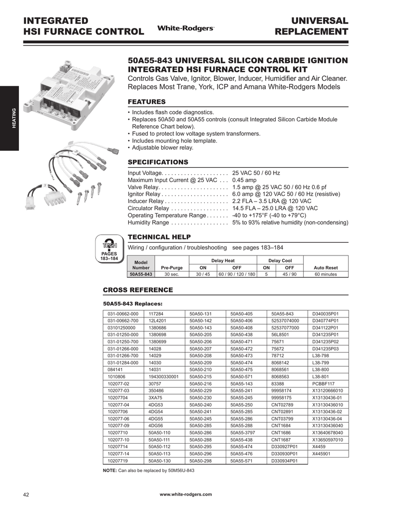
50a55 486 Wiring Diagram
Vt Commodore Ignition Wiring Diagram, Complete Wiring Diagrams For Holden Commodore VT, VX, VY, VZ, VE, VF, 5.36 MB, 03:54, 32,796, John Amahle, 2018-08-01T19:37:41.000000Z, 19, Vt Commodore Ignition Wiring Diagram, to-ja-to-ty-to-my-to-nasz-swiat.blogspot.com, 1272 x 1800, jpeg, bcm pcm 12j swiat nasz, 20, vt-commodore-ignition-wiring-diagram, Anime Arts
It seems that the 5a fuse on the board keeps blowing? The condensor initiates and then shuts down (presumably from the no blower start, i opened the unit up and looked at the board and found the blown fuse, i replaced the fuse but as soon as i turn. Refer to the wiring diagram and wiring table when connecting the 50a55 control to other components of the system. Refer to the wiring diagram and wiring table when connecting the 50a55 control to other components of the system.
Refer to the wiring diagram and wiring table when connecting the 50a55 control to other components of the system. Ul approved, 105°c rated 18 gauge, stranded, 2/64 thick insulation wire is recommended for all low voltage safety circuit connections. Refer to 50a55 specification sheet for recommended terminals to mate with those on the control. Ul approved, 105°c rated 18 gauge, stranded, 2/64” thick insulation wire is recommended for all low voltage safety circuit connections. Refer to 50a55 specification sheet for recommended terminals to mate with those on the control. Refer to the wiring diagram and wiring table when connecting the 50a55 control to other components of the system. Ul approved, 105°c rated 18 gauge, stranded, 2/64″ thick insulation wire is recommended for all low voltage safety circuit connections. Refer to 50a55 specification sheet for recommended terminals to mate with those on the control. Short or incorrect wiring will damage thermostat and could cause personal injury and/or property damage.
Just installed a 50A55-486 in place of the 50, Sorry, did not get all written down. I just
Just installed a 50A55-486 in place of the 50, Sorry, did not get all written down. I just

Just installed a 50A55-486 in place of the 50, Sorry, did not get all written down. I just

Just installed a 50A55-486 in place of the 50, Sorry, did not get all written down. I just

White Rodgers 50a50 241 Wiring Diagram - General Wiring Diagram

50A52-102 vs 50A55-486 furnace and AC control module - DoItYourself.com Community Forums

White Rodgers 50a50 241 Wiring Diagram - General Wiring Diagram

White Rodgers 50A55-474, 50A55-571 User Manual

White Rodgers 50a50 241 Wiring Diagram - Ekerekizul
White Rodgers 50a50 241 Wiring Diagram - General Wiring Diagram
