36 Volt Trolling Motor Battery Wiring Diagram

Vt Commodore Ignition Wiring Diagram, Complete Wiring Diagrams For Holden Commodore VT, VX, VY, VZ, VE, VF, 5.36 MB, 03:54, 32,796, John Amahle, 2018-08-01T19:37:41.000000Z, 19, Vt Commodore Ignition Wiring Diagram, to-ja-to-ty-to-my-to-nasz-swiat.blogspot.com, 1272 x 1800, jpeg, bcm pcm 12j swiat nasz, 20, vt-commodore-ignition-wiring-diagram, Anime Arts
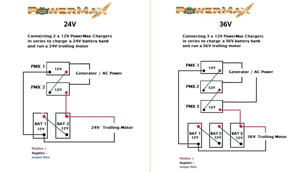
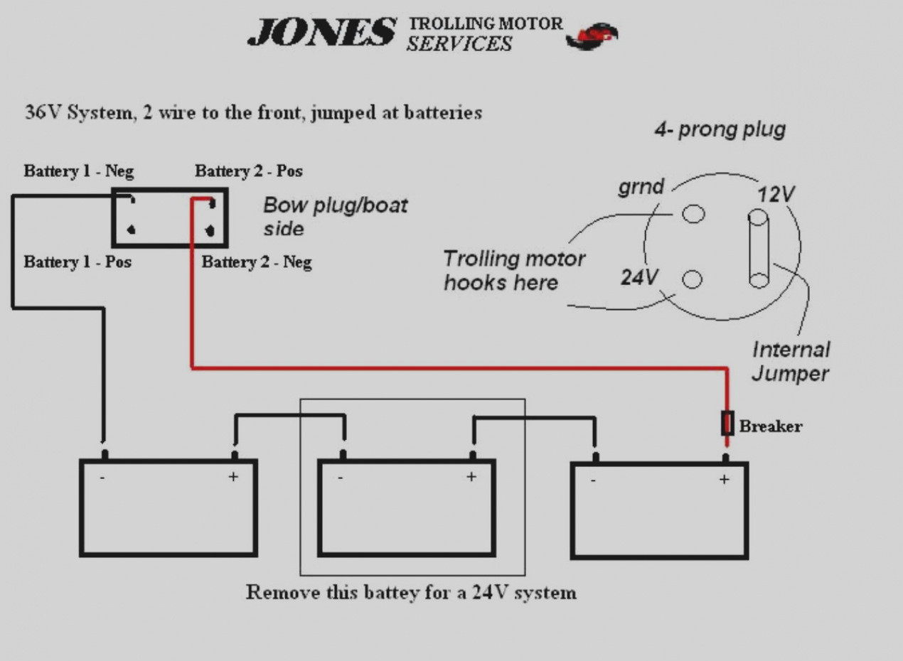
Wiring a 36v battery is relatively simple, especially compared to wiring three 12v batteries in a series. First, connect the positive (red) terminal of the. Each battery has a positive terminal which is red in color and a negative terminal which is black in color. Using a battery connector cable, connect.
Eliminate the dual battery switch as it is not needed in either of your scenarios. The second diagram shows how to take 12 volts off a 24. 36 volt systems (3 batteries): Make sure that the. Leave a comment / trolling motor / by btm. Installation diagrams 36 volt system the following schematic outlines the necessary accessories/cables needed to connect a trolling motor 1 to a 36 volt system. 3 12 volt battery (need 2) 4 circuit breaker. Installation diagrams 36 volt system the following schematic outlines the necessary accessories/cables needed to connect a trolling. Make sure that the trolling motor is disconnected.
36v Trolling Motor Wiring

36v Trolling Motor Wiring
Wiring Diagram For 36 Volt Trolling Motor

24 and 36-volt Wiring Diagrams – TrollingMotors.net

36v Trolling Motor Wiring

36 Volt Series Trolling Motor Connection Kit with On-board Charging (RCE36VBCHK) in 2021

36v Trolling Motor Wiring Diagram - AKADEMINEKERJADIRUMAH

36v Trolling Motor Wiring
36 Volt Trolling Motor Wiring Diagram - Wiring Diagram
