4 Wire Photo Sensor Wiring Diagram
Vt Commodore Ignition Wiring Diagram, Complete Wiring Diagrams For Holden Commodore VT, VX, VY, VZ, VE, VF, 5.36 MB, 03:54, 32,796, John Amahle, 2018-08-01T19:37:41.000000Z, 19, Vt Commodore Ignition Wiring Diagram, to-ja-to-ty-to-my-to-nasz-swiat.blogspot.com, 1272 x 1800, jpeg, bcm pcm 12j swiat nasz, 20, vt-commodore-ignition-wiring-diagram, Anime Arts
Connect the black, white, and red wires from the light sensor to the wall wires. Twist the hot black wires together and screw a plastic wire nut onto the ends. Repeat this for the neutral white wires and red load wires. [3] the live and neutral wires are.
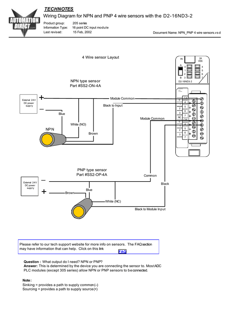
Module common brown black to input blue. External 24v+ dc power supply. External 24v dc power supply. Common module common blue brown black black to module input. 2 wire knock sensor wiring diagram 2 wire knock sensor wiring diagram. The knock sensor has two wires, one for the signal and one for the ground. When the knock sensor detects a knocking noise, it sends a signal to the ecu (engine control unit) to adjust the fuel injection and ignition timing accordingly. For example, we will reference an inductive proximity sensor. When a target, the object that a sensor is detecting, comes within sensing range of the sensor, the sensor output turns on and current flows.
4 Wire Proximity Switch Wiring Diagram - Wiring Diagram
Wiring diagram for NPN and PNP 4 wire sensors and D2-16ND3-2

4-wires Pnp Label Detection Photoelectric Fork Label Sensor For Package Machine - Buy Fork Label

4 Wire Motion Sensor Light Wiring / Ceiling Occupancy Sensor Wiring Diagram | Review Home Co

How to design fully isolated 4-wire sensor transmitters - Precision Hub - Archives - TI E2E
4 Wire Motion Sensor Light Wiring : 4 Wire Motion Sensor Light Wiring Diagram - Wiring Diagram

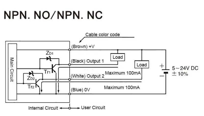
4 Wire Proximity Sensor Wiring Diagram - Wiring Schema

RTD Sensor Wiring | TC Inc

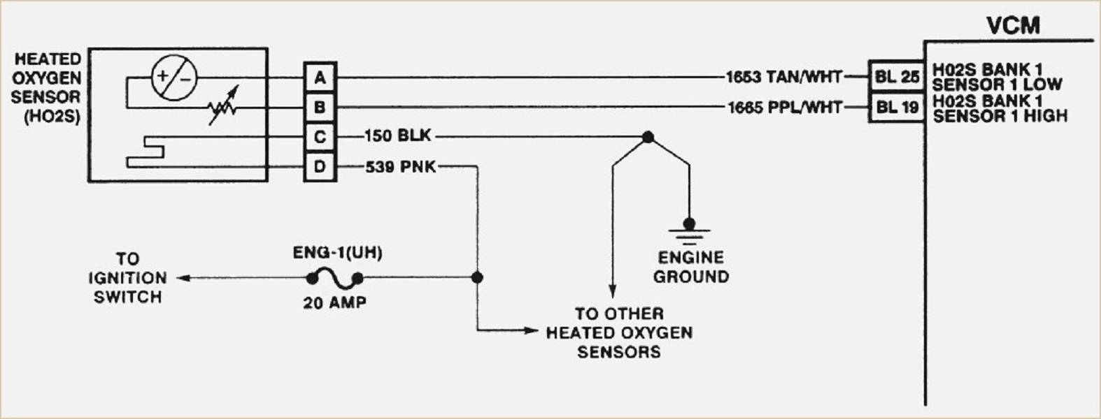
4 Wire O2 Sensor Wiring Diagram - Cadician's Blog

4 Wire O2 Sensor Wiring Diagram Downstream Dodge
